Lens distortion
In real case scenarios there is the need to model the effect of lens distortion on the image
there are 2 principle types of distortion:
In order to account this types of distortion the model is adjusted accordingly:
$$ \begin{bmatrix} x_{’}\ y_{’}\ \end{bmatrix}= L(r) \times \begin{bmatrix} \overset{\sim}x \ \overset{\sim}y \ \end{bmatrix} + \begin{bmatrix} d\overset{\sim}x \ d\overset{\sim}y \ \end{bmatrix} $$ Where the non-distorted coordinates ($\begin{bmatrix}\overset{\sim}x \ \overset{\sim}y \ \end{bmatrix}$) are mapped to distorted coordinates ($\begin{bmatrix}x_{’} \ y_{’} \ \end{bmatrix}$) through a non linear function $L(r)$ of the distance from the distortion center $r= \sqrt{(\overset{\sim}x - \overset{\sim}x_{c})^2+(\overset{\sim}x - \overset{\sim}x_{c})^2}$
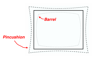
The $L(r)$ function is defined for positive values of $r$ only and for $r =0 \space L(r) =1$. This non linear function is approximated by it’s Taylor series:
$$ L(r) = 1 + k_{1}r^2+ k_{2}r^4+ k_{3}r^6 …. $$
The tangential distortion is approximated as follows
$$ \begin{bmatrix} d\overset{\sim}x \ d\overset{\sim}y \ \end{bmatrix} = \begin{bmatrix} 2p_{1}\overset{\sim}x\overset{\sim}y + p_{2} (r^2 + 2\overset{\sim}x^2) \ p_{1} (r^2 + 2\overset{\sim}x^2) +2p_{2}\overset{\sim}x\overset{\sim}y \ \end{bmatrix} $$
The radial coefficients $k_{1} k_{2}….$ the optical center $(x_c,y_c)$ and the tangential distortion coefficients $p_1,p_2$ are the set of lens distortion parameters that need to be accounted for a realistic modeling of the camera. (for the sake of simplicity the distortion center is taken to coincide with the optical center)