Stereo camera calibration
Why not calibrate both cameras with zhang
In order to calibrate a stereo camera system the $PPM$ alone is not sufficient, the rigid motion between cameras is also needed, a first approach could be to compute the zhang’s method for both cameras but this approach as one major flaw, is not robust to noise
Better solution: guessing
a more robust solution is to make an initial guess of $R$ and $T$ by taking pictures of the same planar pattern from the same position with both cameras and then refine the guess by a non-linear minimization of the reprojection error.
The first guess is obtained as the median between the $R_{i}$ $T_{i}$ computed by chaining the transformations $G_i(G_j^{-1})$
Then the guess is refined with Levenberg-Marquardt algorithm
$$ \sum_{k=L}{\sum_{i=1}^{n}{\sum_{j=1}^{m}\Vert m_{i,j}^{k} - \overset{\sim}m(A_{L},A_{R},K_{L},K_{R},R,T,w_{j}) \Vert^{2}}} $$
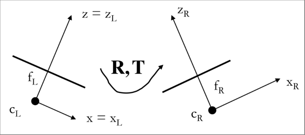
Then for convenience one of the 2 CRF is chosen to be the stereo camera reference frame (SRF), the other camera $PPM$ matrix can be retrieved by the rigid motion matrix $R,T$ between the 2 cameras
$$ \overset{\sim}P_{L} = A_{L}[I|0] \Rightarrow \overset{\sim}P_{R} = A_{R}[R|T] $$
Rectification
For better searching for correspondent points the images need to be perfectly aligned, this is impossible with mechanical alignment so the images are rectified This is done by virtually rotating the calibrated cameras (e.g. redefining the $PPMs$ ) about their optical center through an homography
Constructing the $a$ matrix
so in order to define a new $PPM$ a matrix $A_{new}$ is arbitrary chosen (e.g. the mean between the $A_{R},A_{L}$)
Constructing the $r$ matrix
Then a new $R_{new}$ matrix need to be defined, the first vector is chosen to be parallel to the baseline vector $B=C_{R}-C_{L}$ that in the stereo reference frame becomes
$$ B = -R^{T}T = [B_{x},B_{y},B_{z}] $$
Then the first vector is taken parallel to the $B$ vector as $r1= \frac{B}{\Vert B \Vert}$
the $Y$ vector is taken to be orthogonal to the $X$ vector and to an arbitrary $k$ that can be the old $Z$ axis:
$$ k = [0,0,1]^{T} \Rightarrow r_{2} = r_{1} \land k = \frac{[-B_{y},B_{x},0]^{T}}{\sqrt{B_{y}^{2} +B_{x}^{2} }} $$
In the end, the new $Z$ axis is perpendicular to the two vectors so
$$ r_{3} = r_{1} \land r_{2} $$
So the new $PPMs$ became:
$$ \overset{\sim}P^{’}{L} = A{new}[R_{new}|0] $$ $$ \overset{\sim}P^{’}{R} = A{new}[R_{new}|- R_{new}C_{R}] $$
Rectification homographies
Both images go trough a rotation and a change of intrinsic parameter, so they are related to the originals through homographies
So for the left camera:
$$ \begin{cases} \overset{\sim}m_{L} = A_{L}[I|0]\overset{\sim}M \ \overset{\sim}m_{L}^{’} = A_{new}[R_{new}|0]\overset{\sim}M \end{cases} \Rightarrow \overset{\sim}m_{L} = A_{L}R_{new}^{-1}A_{new}^{-1}\overset{\sim}m_{L}^{'}
$$ $$ H_{L} = A_{L}R_{new}^{-1}A_{new}^{-1} $$
for the right image is convenient to move the origin of the WRF into the optical center of the camera
$$ \begin{cases} \overset{\sim}m_{R} = A_{R}[R|0]\overset{\sim}M_{R} \ \overset{\sim}m_{R}^{’} = A_{new}[R_{new}|0]\overset{\sim}M_{R} \end{cases} \Rightarrow \overset{\sim}m_{R} = A_{R}RR_{new}^{-1}A_{new}^{-1}\overset{\sim}m_{R}^{'}
$$ $$ H_{R} = A_{R}RR_{new}^{-1}A_{new}^{-1} $$
Getting back to 3d coordinates
with a calibrated stereo system the depth information and also 3D coordinates can be estimated, so given the relation between 3D point and image points
$$ p^{*} = \begin{bmatrix} a_{u}x +u_{0}z \ a_{v}y +v_{0}z \ z \end{bmatrix} = AP = \begin{bmatrix} a_{u} & 0 & u_{0}\ 0 & a_{v} & v_{0}\ 0 & 0 & 1\ \end{bmatrix} \begin{bmatrix} x \ y \ z \ \end{bmatrix} $$
The coordinates can be retrieved by the following expression
$$ P = A^{-1}p^{*} $$
multiplied by $z$
$$ P = zA^{-1}\frac{p^{}}{z} $$ But $\frac{p^{}}{z}$ is the vector of the image coordinates
$$ \frac{p^{*}}{z} = \begin{bmatrix} a_{u}\frac{x}{z} +u_{0} \ a_{v}\frac{y}{z} +v_{0} \ 1 \end{bmatrix} = \begin{bmatrix} u \ v \ 1 \end{bmatrix} $$
and given the $A^{-1}$ matrix
$$ A^{-1} = \begin{bmatrix} \frac{1}{a_{u}} & 0 & - \frac{u_{0}}{a_{u}}\ 0 & \frac{1}{a_{v}} & - \frac{v_{0}}{a_{v}}\ 0 & 0 & 1\ \end{bmatrix} $$
The 3D coordinates can be computed as follows
$$ P = zA^{-1}p $$
Now it’s also possible to compute an image point $P$ of a given 3D space taken by another camera by getting the 3D coordinates and then translating by a rotation and a translation function
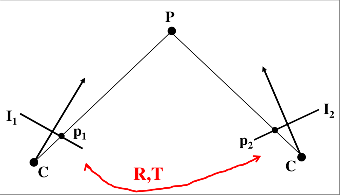
$$ p_{2} = AT_{1\rightarrow 2}(zA^{-1}p_{1}) \space with \space T_{1\rightarrow 2}(P_{1}) =RP_{1} + T $$
It’s also possible to compute it between different cameras
$$ p_{2} = A_{2}T_{1\rightarrow 2}(zA_{1}^{-1}p_{1}) \space with \space T_{1\rightarrow 2}(P_{1}) =RP_{1} + T $$